-
SCOPE will be communicating with RUDAK-U and IHU primarily using CAN interface. But it also has RS485 multi-drop serial port to communicate with RUDAK-U as a backup link. Shown here on the scope is the transmission from SCOPE to CONSOLE (middle four div., lower level) and from CONSOLE to SCOPE (right two div., higher level).
-
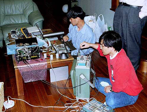
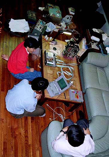
Hiroyuki Ohata JM3MAJ (left) and Yoshi Takeyasu JA6XKQ (right) try to identify the cause of boot problem of Camera-B by observing signal on the link. The synchronous scope used here used to serve also for JAS1(FO12) project.
-
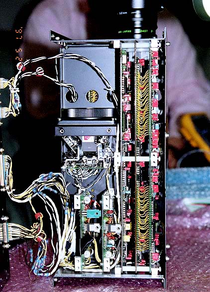
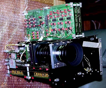
SCOPE FM with its side panel removed, showing inside of the SCOPE flight hardware. From right most to middle : A/D board, Memory board and CPU board for Camera-B (wide angle). Top left : CCD block (w/o lens) for Camera-A (narrow angle). Lower left: Two small switching power supply boards for Camera-A.
-
Hiroyuki (holding EM CPU board) and Yoshi (behind the flight hardware) confirm the location of check points on the CPU board of troubling Camera-B.
-
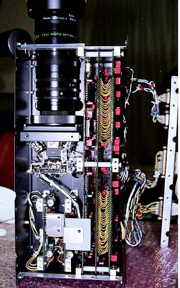
SCOPE FM with its side panels removed, showing inside of SCOPE flight hardware. From right most to middle : A/D board, Memory board and CPU board of Camera-A (narrow angle). Top left : CCD block and flight lens of Camera-B (wide angle). Lower left: Two small swtching power supply boards for Camera-B.
-
Yoshi solders a capacitor while Hiroyuki (left) and Miki Nakayama JR1SWB (right) holding the module.
-
Two isolation diodes in the 10V supply lines are molded in the holes of an aluminum block, and the block is thermaly connected to the module case with an aluminum heat bridge. You can see a part of the dichroic mirror (covered with three CCDs and driver circuit) portion of the CCD block for Camera-B.
-
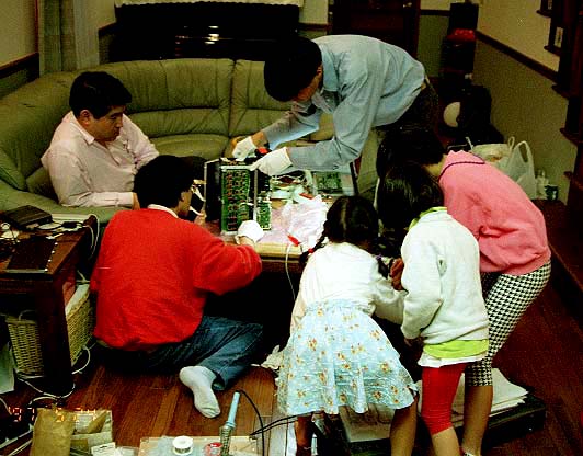
Three little volunteers (from left Sae, Lei and Ellie) try to figure out how synchronous scope works. Next generation?
-
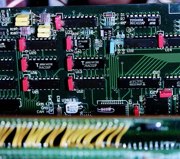
Part of the flight CPU board for Camera-B. RS485 driver circuit, CAN interface chip and CAN filter are visible.
-
Close up of above picture. It shows the criminal = R20. It should not be left there.
-
After the surgical operation. Legs of the resistor successfully removed but we gave up removing its body. The resister body adheres to the board with conformal coating and removing the body could damage the narrow pattern running underneath it.
-
The cause of problem identified and corrected. Relaxing with releaf. From left : Yoshi JA6XKQ, Hiroyuki JM3MAJ and Miki JR1SWB.
-
Hiroyuki (left) and Yoshi look at the screen of console program to confirm the result of their work.
-
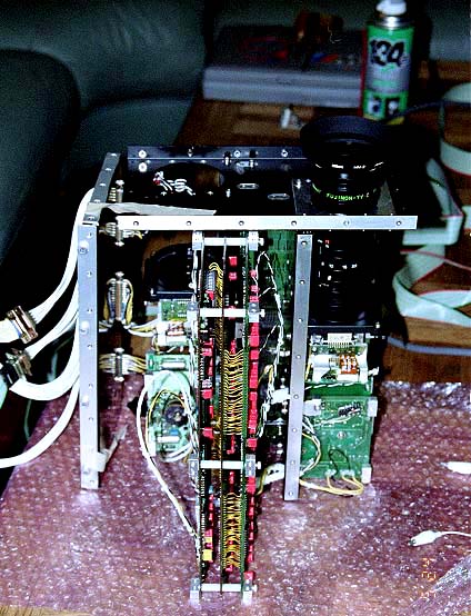
SCOPE FM with its board set for Camera-B extracted. Three identical patterns on the board are A/D converters for Red, Green and Blue.
-
SCOPE FM with its board set for Camera-B extracted.
-
Yoshi (left) and Hiroyuki check a snapshot of ceiling light captured with Camera-A.
-
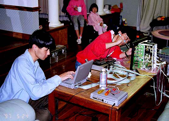
Yoshi touches up the flight CPU board of Camera-B while Hiroyuki upgrade his console program. His console program can boot and excercise all the functions of the SCOPE via RS232, RS485 and CAN bus.
-
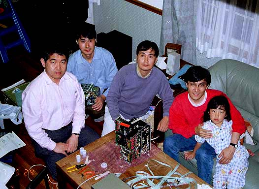
From left: Miki Nakayama JR1SWB, Hiroyuki Ohata JM3MAJ, Tak Okamoto JA2PKI, Yoshi Takeyasu JA6XKQ and Sae.
SCOPE team thanks to Saeko Okamoto for serving us well and forgiving us to mess around the living room (again).
Text and photos by JA2PKI. Photos scanned by JG3XOD.
