The Proposal about Modification of Drake2880 MMDS Downconverter
by Shiro Yoshida JI5MFZ
JAMSAT Newsletter Vol.29-No.3
Translated by JI1IZR, JH7BZR, JF6BCC
1. Reconstruction Object
The original circuit of 2880 is designed for broad-passband use. For the purpose of AO-40 converter, it is useful for you to make its pass-band narrow. The original first stage of RF-AMP amplifier has a good performance as about 1.4dB/NF, so we use it as it is. And we add the 2nd RF stage with MMIC (ERA-3 of Minicircuit, NF:3.2dB, Gain: approximately 17dB at@ 2.4GHz) to increase the total gain of RF stages up to about 32dB.
This will reduce the bad effect on the losses in the stages after the BPF. I set the target NF as 1.8dB. I also designed modification with fewer parts as easy and simple as possible. And I made the modification with changing a small chip resistor as it only effect on the total gain, not on another performance. And I also designed it for power saving and smaller return-loss.
2. RF AMP section
If you do not have any equipment for measurement/adjustment, you should not touch anything on the first RF stage! It is very critical part. See figure (1) and (2) to modify the micro-strip line of RF stage with additional ERA-3.
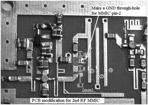
Fig. (1) Cut the micro-strip line between RF and BPF for additional MMIC
1) Make a through-hole GND just beside the strip line using an eyelet, and then put a through-hole pin. It becomes a GND for MMIC pin-4.
2) Cut the GND pin-4 lead at 1.5mm length. Then cut all the other lead of MMIC at 1.0mm. All lead should be preformed to fit the surface of the substrate before the soldering.
3) Put a chip-capacitance of 10-15pF. You can get it from the first stage of IF stage where you removed it (see 4-(1)).
4) Make a bias line (power feeding line) with 0.25mm diameter, 18mm length short wire, and put it between the +5V point and pin-3 of MMIC. The bias should be supplied through 39ohm chip-resistor. This wire should be as close as possible to the surface of the substrate. See figure (2) for details. After you finished all modifications, fix it with a few adhesives.
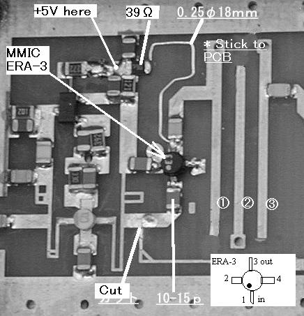
Fig.(2) Modified RF stage with MMIC.
3. BPF section.
You do not need anything to modify this part. Without the modification, the pass-band peak is at 2,500MHz, but it is all. If you do not feel good, extend the length of BPF element as the element(1) should be 19.7mm and the element(2) should be 19.2mm.
4. IF section
Modify it into a single stage design. Please refer to the figure (3) and (4) to remove some unnecessary parts. The two parallel 68ohm chip resistors are in the power line for unnecessary transistor circuit. Remove the resistors for power saving.
The points are;
1) Replace the 15pF chip-cap of C1 with 200pF chip-cap connected to the emitter of 1st IF. It determines the resonant frequency of IF at 145MHz.
2) Replace the R1 510ohm with 51ohm (use it from the removed parts).
3) Makeup a pi-ATT using R2 150ohm and R3 68ohm chip-resistors. See figure (3) or (4) for details.
You can adjust the total gain with changing the value of R1 and R4. But the figured value brings the best result I think.

Fig.(3) Modified IF stage (without IF DC-power biasing)
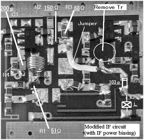
Fig.(4) Modified IF stage (with IF DC-power biasing)
5. Measurement result of IF section (dB)
Freq.
(MHz) |
(A) |
(B) |
(C) |
(D) |
| Gain | R/L | Gain | R/L | Gain | R/L | Gain | R/L |
50 |
10.4 |
5.5 |
10.0 |
5.7 |
-2.2 |
>25 |
-2.8 |
>25 |
100 |
20.9 |
10.5 |
19.3 |
12.0 |
9.7 |
>25 |
8.1 |
>25 |
144 |
27.9 |
12.2 |
22.7 |
20.0 |
16.1 |
>25 |
11.4 |
>25 |
145 |
27.9 |
12.2 |
22.7 |
20.0 |
15.9 |
>25 |
11.3 |
>25 |
146 |
27.9 |
12.2 |
22.7 |
20.0 |
15.8 |
>25 |
11.3 |
>25 |
150 |
27.6 |
11.5 |
22.5 |
19.2 |
15.2 |
>25 |
11.0 |
>25 |
200 |
21.6 |
11.2 |
19.1 |
13.4 |
8.4 |
23.5 |
6.8 |
24 |
300 |
15.1 |
11.5 |
13.7 |
11.9 |
2.1 |
23 |
1.3 |
23 |
* R/L : Output return loss
| |
R1(ohm) |
Output |
(A) |
51 | without Pi-ATT |
(B) |
510 | without Pi-ATT |
(C) |
51 | as figure(3),(4) |
(D) |
510 | as figure(3),(4) |
6 Comprehensive Performance
Freq.
(MHz) |
Style-1 |
Style-2 |
Style-3 |
| Gain | NF | Gain | NF | Gain | NF |
2,300 |
7.0 |
- |
23.5 |
- |
11.0 |
- |
2,350 |
19.6 |
- |
33.7 |
- |
22.0 |
- |
2,400 |
26.0 |
1.80 |
37.4 |
1.79 |
24.5 |
1.79 |
2,450 |
27.7 |
- |
35.9 |
- |
22.9 |
- |
2,500 |
26.1 |
- |
29.2 |
- |
17.1 |
- |
2,550 |
23.6 |
- |
23.6 |
- |
11.3 |
- |
2,600 |
21.1 |
- |
18.6 |
- |
6.1 |
- |
2,650 |
18.9 |
- |
17.3 |
- |
1.0 |
- |
Style-1 modification: Original BPF and IF (C) modification. <- **Recommended style**
Style-2 modification: Extended BPF and IF (A) modification.
Style-3 modification: Extended BPF and IF (D) modification.
Measured at the room temperature of 20 degrees Centigrade.
7 Others
I suggest the Style-1 is the most simple and the easiest modification without any adjustment.
The extension of BPF with 2 stage RF modification will bring the over gained condition. It will cause self-oscillation problem in a shield box. In this case, please try to put some RF absorption pad at the inside of the shield-case.
You can adjust C1 (200pF) of IF to get the peak gain at 2400MHz.
8 At The Last
I think that, the most effective usage of Drake2880 is just modify the IF stage only, and use with a good performance preamp. If the preamp has performance of 0.5dB/NF and 15dB Gain, the total NF will be 0.77dB. It is a very good performance.
The NF of IF-modified only Drake2880 is about 5dB. This means that the noise temperature will be improved dramatically from 627K to 51.6K with good preamp. The performance of your receiving system is better about 12 times than no preamp
I appeare that many people have a wonderful "ear" and enjoys satellite communication comfortably.
If you have questions, please e-mail to Yoshihiro Imaishi JF6BCC in English or Japanese. Please note that Mr. Yoshida JI5MFZ will not accept any direct request, and will not have any responsibility about this English version article.
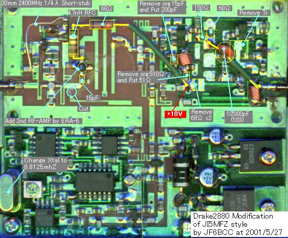
From translator:
Here is the image of my modified Drake2880. This is the same style of this article, but I used MMIC ERA-5 for the second RF amp. ERA-5 requires +5V power source so I changed some for it. It is working very well now.