| JAMSAT SCOPE Project |  |
The JAMSAT SCOPE Project
JAMSAT The Japan AMSAT Association
SCOPE Project Team 1. Background
SCOPE is an acronym for "Spacecraft Camera experiment for Observation of Planets and the Earth". In 1990, at the first satellite builders meeting where the Phase-3D project began, JAMSAT made a proposal to have full color CCD digital cameras as an onboard experimental module. Noting Phase-3DÅfs distinctive 3 axis stabilization feature, people attending the meeting showed interest in this plan and encouraged JAMSAT to proceed. In 1991, at the second satellite builders meeting, JAMSAT described its brief specifications and spacecraft resources of 5 Kg of weight, 5 litters of volume, and 5W of power were reserved for it.Originally SCOPE consisted of three cameras, one each with telescopic, narrow and wide angle lenses. As the design of the spacecraft made progress its limited weight and volume allowance made it difficult to put three cameras on board. Also the study of the satellite stabilization system concluded that pointing at planets with the accuracy required to capture their image with the telescopic lens was not feasible. With regret we decided to drop the camera with the telescopic lens. The project moved from its concept design phase to detailed hardware design. In late 1993 a breadboard model was built to prove the concept of its design and operation. In 1994 and 1995 the team built several engineering models to evaluate its design in detail and to pick a specific design. As a result the design of the flight model (FM) was fixed and the team entered the phase of procurement and assembly of the flight and flight backup hardware. During this period the team had discussions with other participating AMSAT groups and modified the design where needed. In 1996 the assembly of the flight model was completed and a series of tests begun for its basic functions and operations in a thermal and vacuum chamber, followed by acquisition of operating characteristic data at different temperatures along with extensive tests for the whole system. In February of 1997, the flight model was delivered to the Phase-3D lab in Orlando where it passed electrical and mechanical fit check. Now the SCOPE project is in its very final phase. 2. MissionThe SCOPE project has the following three objectives.
3. System3.1 Mechanism
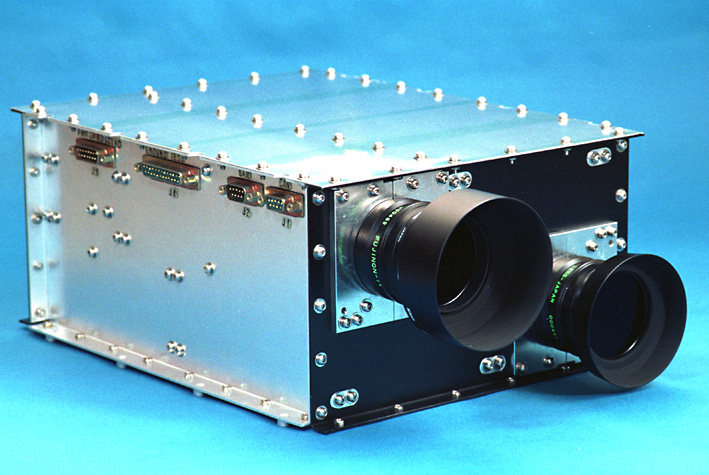
Two individual cameras Camera-A with a narrow angle lens and Camera-B with a wide angle lens are housed in a single module case. The original plan was to house each camera in an individual module case. However weight and space limitations of the spacecraft required two cameras to share one module case.The size of module case is 297(D) x 227(W) x 130.6(H) mm and is standard among other modules except for its height. The mass of the SCOPE module with its two cameras is 5.4 kg and is as light as our original estimate of each single camera module. This is the result of our diet effort (mass and volume reduction). 3.2 Electronics
The electronics system consists of four sections, CCD head, CPU, Memory, A/D converter and Power Supply.3.2.1 CCD head
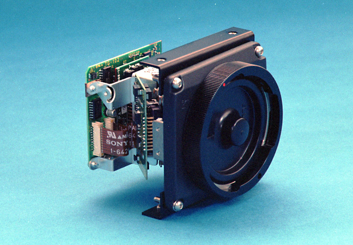
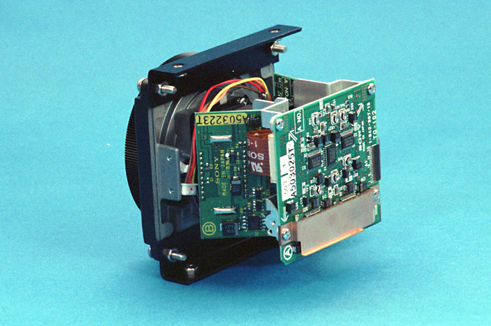
We originally planned to use a frame transfer CCD with an on-chip stripe color filter. This type of CCD simplifies the design of circuits around it but we found that its color filter, which is made of organic material, deteriorates quickly in the severe space environment and we decided not to use this type of CCD. Instead we used a 3 CCD head from a PAL standard camera used in the industrial image processing field. This CCD head consists of a dichroic mirror to separate the colors and three inter-line transfer CCDs for red, green and blue. The dichroic mirror is a kind of prism and is stable in a space environment since it does not use any organic material.Specification of the CCD is as follows:
These CCD heads are commercially available as spare parts for an industrial grade PAL standard camera and were modified to be driven directly from the CPU. 3.2.2 Optics
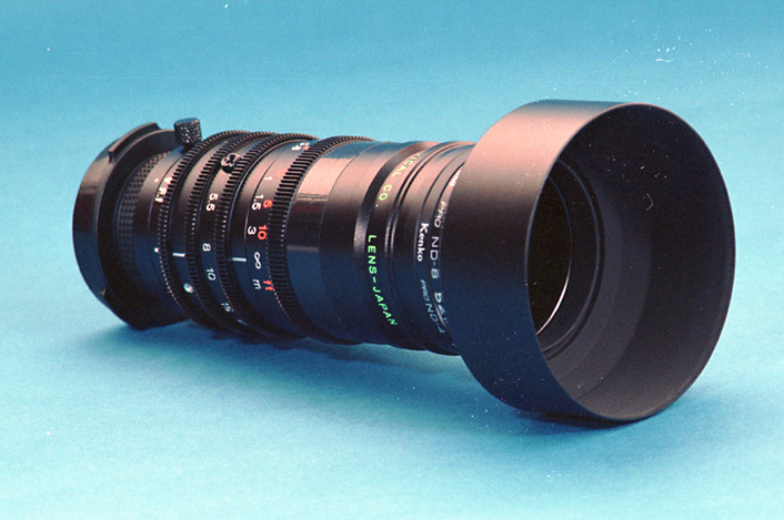
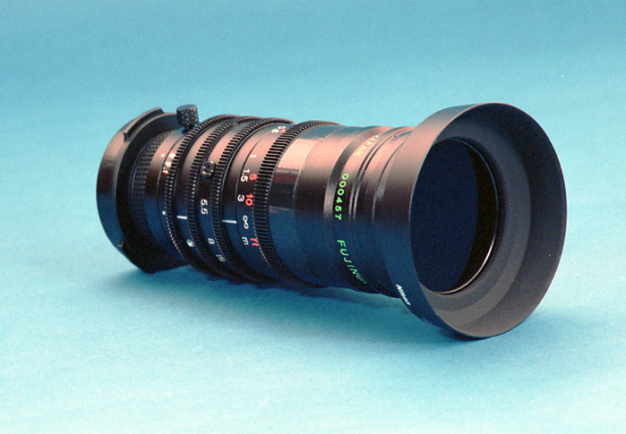
Commercial off the shelf zoom lenses which were designed for the CCD head were employed. The zoom is not adjusted in space but is set before launch to a specific focal length determined by a study for obscuration from a nearby object (V band antenna) on the spacecraft and the viewing angle from the final orbit. The zoom will be fixed when the final orbit characteristics are determined. The two cameras have the same zoom lens with different zoom ratio settings to provide narrow and wide view angles.The front clear aperture of the lens is 41.5 mm, and the planned field of view (FOV) of Camera A is 16 degrees and FOV of Camera B is 32 degrees. ND (Neutral Density) filters will be used to adjust for the relative brightness of the earth. Three filters each with x4, x8 and x8 factor are employed for both optics providing x256 factor number. Those ND filters and hood are modified commercial products. The lubricant used in commercial lenses could evaporate causing fatal contamination. The flight lenses were taken apart, cleaned and reassembled using space grade lubricant. The focus is adjusted to a vacuum environment by taking the difference in refraction into account. At this writing, the final orbit parameters have not been determined. However with assumtion of apogee height of 47000km and perigee height of 4000km gives following calculated resolution of objects on Earth. Camera-A : 25km/pixel @ apogee, 4.6km/pixel @ perigee Camera-B : 50km/pixel @ apogee, 9.2km/pixel @ perigee 3.2.3 CPU section
To simplify circuitry, SCOPE uses a TMP68301 chip that is built around a 68000 CPU. This chip has 3 channels of UART, timer/counter, address decoder, wait generator, interrupt controller and 16 bit parallel I/O port all integrated in a single chip.The CPU clock is selectable between 16 Mhz or 8 Mhz which helps reduce power consumption. A initial program loader is stored in an AMSAT space proven HM-6617 fused link ROM. This kind of ROM is known to be stable even in the space environment. Conventional EPROMS used in most ground based electronic devices like computers should not be used for space applications because charged particles may affect the data written in them. Each SCOPE camera has two sets of fuse link ROMs for redundancy. The CPU section also contains an RS-485 async port and CAN bus (Control Area Network) interface to be used to communicate with other onboard modules for program loading, commanding and transferring picture data. 3.2.4 Memory section
The memory section has 4 MB of HM628512 SRAM (Static RAM) in total. Within this 4 MB, 1 MB has EDAC (Error Detection And Correction) capability utilizing a IDT39C60 to detect and correct unwanted changes of data caused by SEU events (Single Event Upsets) which are normal in the space environment.Unwanted changes in program code can cause the system to crash. Thus the program code will be loaded into the EDAC memory area and less sensitive image data will be stored in the non-EDAC portion of memory. 3.2.5 A/D converter section
The A/D converter section has three identical A/D converters, one each for the red, green and blue CCD. Each A/D converter has 8 bit resolution and with three of them 24 bit (16.7 million colors) will be reproduced.There is a variable gain amplifier (x1 - x8) between each CCD and A/D converter to adjust the signal level. Output from the A/D converters is stored in 3 MB of non-EDAC memory by the CPU. The A/D converter section also contains driver circuits and temperature monitor circuits for the CCD block. 3.2.6 Power Supply section
The power supply section receives +10.6V from the satellite power bus and supplies +5V, +15V and -9V to other SCOPE sections. LM2577 switching power supply ICÅfs are configured as a flyback type power supply. To improve load regulation two similar power supplies are used, one supplies +5V only and the other supplies +15V and -9V. Power consumption is around 5W/camera and is very close to the original estimation.4. Interface with other onboard systems
Other systems closely interfacing with the SCOPE cameras are the IHU (Integrated House-keeping Unit) and RUDAK-U.A single bit switched by the IHU turns on and off each camera. SCOPE communicates with RUDAK-U via the CAN-bus or a RS-485 multi-drop serial link. SCOPE serves as eyes for RUDAK-U and RUDAK-U serves as ears and voice for SCOPE. SCOPE listens for boot load code as well as commands from the ground command station via RUDAK-U through the CAN-bus. Images captured by SCOPE will be stored in RUDAK-U and then later forwarded down to ground stations. An RS-485 multi-drop link serves as a backup to the CAN bus and links RUDAK-U and the two SCOPE cameras. 5. The SCOPE Your eyes in space
The SCOPE cameras to be flown aboard the Phase-3D satellite will become your eyes in space. JAMSAT has been dreaming about having such eyes in space, eyes that show us real color images of our Mother Earth.The JAMSAT SCOPE project team expresses our sincere thanks to our membership and to members of our Phase-3D support group who have been supporting the Phase-3D project. It has given us great joy to work with the talented SCOPE project members and people from other participating AMSAT organizations. JAMSAT SCOPE PROJECT TEAM
Original text by JA6XKQ. JA2PKI is responsible for translation, some part of the text and this HTML file. Special thanks to WD0E for Englishnization of the document. (C) 1997 JAMSAT
Updated Sep. 30, 1998 (C) 1998 JAMSAT |
|
 |
|